Highly sensitive seismometer
Context: Gravitational wave detectors are very sensitive to seismic noise, as it limits the sensitivity in the low frequency band (< 10Hz). While this kind of noise can be attenuated for many orders of magnitudes with the use of mechanical filters, it is impossible to completely get rid of it on the ground. The only way to overcome this problem is to build the detector in space, like it will happen for the Laser Interferometer Space Antenna (LISA), one of the next generation gravitational wave detectors. For this reason all ground based gravitational wave detectors use seismometers placed around the detector to monitor the seismic activity in the area and evaluate the effect on the detector signal.
Project:
The student will build a very sensitive seismometer. The device will be composed of a mechanical movable part and an electronic part. The mechanical part is composed of a needle balanced on a small magnet. The needle movements, caused by seismic activity, will be converted into an electronic signal through a coil. The signal will be then amplified and converted in a digital signal that can be visualized on a computer with the help of specific softwares.
Once the device has been built the student will measure its efficiency analyzing the response to a vibrational motion created with different masses at different distances.
Multi-stage pendulum
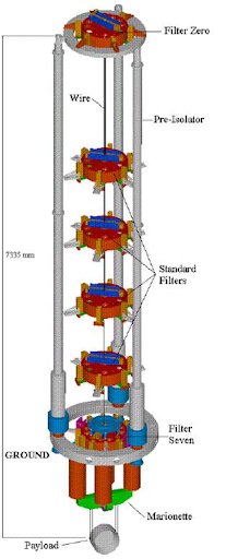
Context: Gravitational wave detectors are very sensitive to seismic noise, which limits the sensitivity in the low frequency band (< 10Hz). In order to reduce the seismic noise some techniques have been developed and are in use in current gravitational wave detectors like AdVirgo and aLIGO. They include for example the use of multi-stages pendulum structure, which reduces the horizontal motion by a factor 1/f2 at each stage. In Fig. 1 the so-called AdVirgo Superattenuator is shown. It is a very complex system, composed of many different active and passive filters including a multistage pendulum. It is 7m meter high and it is able to reduce the seismic noise by 12 orders of @10Hz.
Project:
The aim of the project is to measure the transfer function of a pendulum with different configuration, and compare them in order to analyze the benefit of a multi-stage pendulum for seismic noise attenuation.
In the first phase of the project the student will build a simple pendulum and will measure its fundamental parameter and the transfer function and resonance frequency when an excitation force is applied at the top. After that, the pendulum will be modified into a multiple stages pendulum in order to see how the additional stages improve the attenuation of the applied force.

Interferometric sensor for “GW-like” signal
Context: Interferometric gravitational wave detectors are basically Michelson interferometers able to measure the difference of the arms lengths with a precision of about 10-18m (@100Hz). When a gravitational wave passes, it will stretch and squeeze the space with opposite effect in the two directions [Fig. 1]. These changes in the arms lengths create an interference pattern in the output of the interferometer, that can be read through a photodiode. Analyzing the output of the interferometer and all the main sources of noise is possible to trace back to the gravitational wave signal.

Project:
In this project the student will build a small Michelson interferometer. The end mirrors will be attached to piezoelectric actuators, that will give control on their movements. The piezo can be used to send a signal to the mirrors and modify their position. The student will study the output of the interferometer and will analyze how it changes when different signals are sent to the mirrors.
In the first part of the project the student will build and characterize the interferometer, analyzing the noises sources that affect the output. Then the mirrors will be moved, sending different kinds of signal to the piezo attached to the mirrors: starting with simple sinusoidal oscillations and ending with a “gravitational wave-like” signal (chirp signal).
“Gravitational” Waves on a Ripple Tank
Overview: Gravitational waves are ripples in the curvature of spacetime predicted in Einstein’s general theory of relativity, first detected in 2015 from the merger of a binary of black holes. Ripples on the surface of water are on the other hand caused by the Newtonian gravitational field of the earth, and are also known as “gravity” waves. They can be produced on a tank of water, such as a wave tank or a ripple tank. This projects brings the two together, and uses gravity waves to simulate gravitational waves. Some of the key features of gravitational waves are common to all of wave physics, and can already be observed in the surface wave simulation experiment.


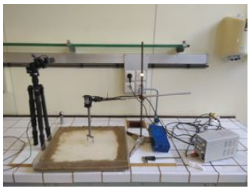
Project description: In previous year’s project we set up a ripple tank to produce “wakes” on the surface of water using a motor [Fig 1, left panel]. These wakes resemble gravitational waves emitted from an inspiralling compact binary. The amplitude of the ripples fall off as one over square root of the distance from the source – this is the idea behind how gravitational-wave sources act as standard distance indicators or “standard sirens.” We investigated what kinds of waves (frequencies, amplitudes) can be produced and detected with our setup. We could also crudely measure the fall-off of the amplitude with distance using a laser sensor.
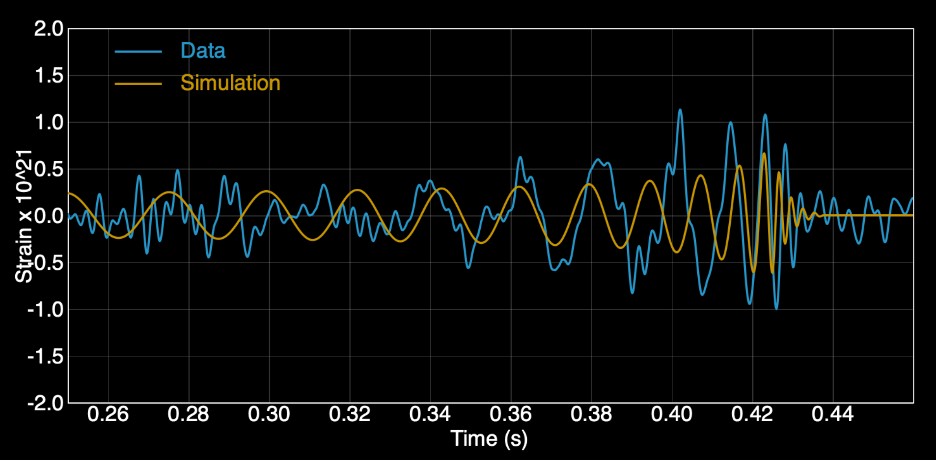
We will follow up on the previous year’s project and try to investigate (i) how to better measure the amplitude of the ripples / wakes, (ii) whether fluids other than water can give us a access to a wider range of frequencies, and (iii) how closely we can produce a “chirp” gravitational-wave pattern [Fig 1, right panel]. The student will compare and contrast the simulation with real gravitational waves. We will eventually move towards having a setup which we can use for public demonstration.